

User Guide
The Domain Message Specification (DMS) is the new style of message specification that replaces the old style Message Implementation Manual (MIM). Although the DMS looks different than the MIM, the differences between the two specification are:
- The DMS covers one domain and only includes common / generic artefacts used by that domain, whereas the MIM contained multiple domains.
- A MIM was released as part of a SPINE release and implemented over TMS.
- A DMS is not bound to either the SPINE or TMS.
This section gives guidance on how to use this specification and identifies the various artefacts and their purpose. Note: because the domain specifications vary slightly in structure, the purpose of all pages or artefacts described may not be present within all specifications.
1 Header and Footer
1.1 Header
1.2 Footer
2 Navigation Tabs
2.1 Navigation Tab behaviour
2.2 Navigation Tab Levels
2.2.1 Level 1 Navigation Tabs
2.2.2 Level 2 Navigation Tabs for Message Definitions Page
2.2.3 Level 2 Navigation Tabs for Generic Page
2.2.4 Level 2 Navigation Tabs for References Page
3 Explanation of purpose of each page
3.1 Overview Page
3.2 Change History Page
3.3 Message Definitions Page
3.4 TMS Implementation Page
3.4.1 Application Role table
3.4.2 Application Role Rule Table
3.4.3 Trigger Events
3.4.4 Interaction Diagrams
3.4.5 Interaction Tables
3.4.6 Message Examples Table
3.5 ITK Implementation Page
3.5.1 Application Role table
3.5.2 Application Role Rule Table
3.5.3 Trigger Events
3.5.4 Interaction Diagrams
3.5.5 Interaction Tables
3.5.6 Message Examples Table
3.6 Configuration Profiles Page
3.7 Generic Page
3.8 Generic CDA Page
3.8.1 Generic Models Page
3.9 Data Type Specifications Page
3.10 Nullification Page
3.11 TMS Infrastructure Page
3.12 TMS Infrastructure CMETs Page
3.13 References Page
3.14 Domain References Page
3.14.1 Data Type Cross References Page
3.14.2 Constraint Cross References Page
3.14.3 Template Cross References Page
3.14.4 Vocabulary Cross References Page
3.15 Nullification References Page
3.15.1 Data Type Cross References Page
3.15.2 Constraint Cross References Page
3.15.3 Template Cross References Page
3.15.4 Vocabulary Cross References Page
3.16 TMS Infrastructure References Page
3.16.1 Data Type Cross References Page
3.16.2 Vocabulary Cross References Page
3.16.3 CMETs Cross References Page
3.17 Glossary Page
4 Icon Meaning
1 Header and Footer
1.1 Header
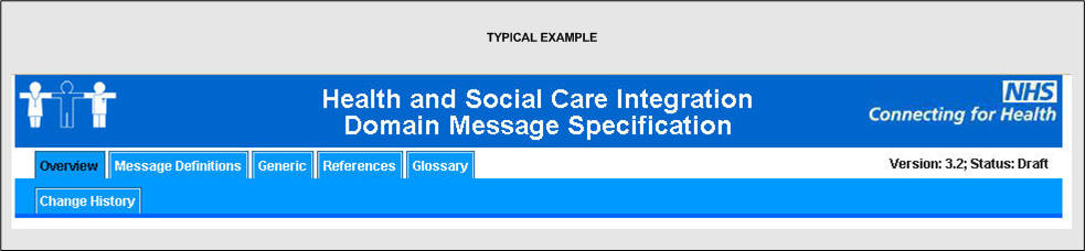
The header contains the following information
- Domain name - The business name of the domain, note there is no definitive definition of domain and this should be read as an area of interest or information flow.
- Version
- first number is major change ,second minor change, although not definitive this should be interpreted as
- major = breaking change
- minor = non breaking change.
- Status
- Draft - (Draft) For information , evaluation and comment, the message specification should not be used for implementation.
- RC"n" - (Release Candidate) A specification issued as fit for purpose but not yet proven through an implementation.
- Final - A full release of the specification which should have been through the development life cycle and is deemed as fully fit for implementation. It will have been proven by a real implementation.
1.2 Footer
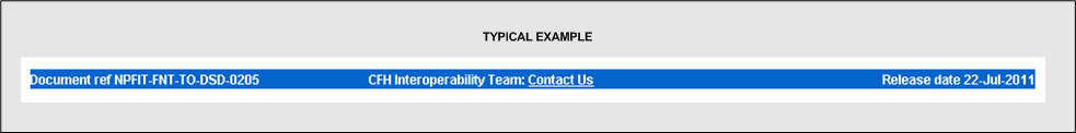
- Document Ref: - A reference number for this Domain specification.
- Release Date: - The date of the release of the specification.
- CFH Interoperability Team Contact Us - An email address of the interoperability Team which authored this specification. This address should be used only where other support contacts are not available.
2 Navigation Tabs
2.1 Navigation Tab behaviour
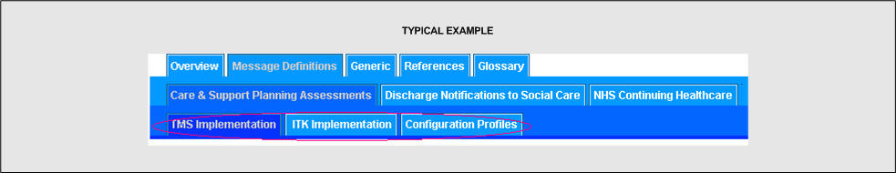
When the mouse is over a tab the font colour changes and a screen tip appears.

When you are viewing a page after clicking on a tab the font changes colour to indicate which page you have selected.
When navigating though multiple tab levels the font colour changes and the different tab background colour gives an indication of where you started from.
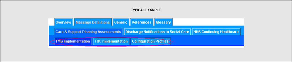
In the example above the trail is Message Definitions -> Care & Support Planning Assessments -> TMS Implementation.
2.2 Navigation Tab Levels
The navigation tabs within the specification are at 3 levels, the following section describes the level 1 tabs. The purpose of the artefacts relevant to each tabbed page is described later.
2.2.1 Level 1 Navigation Tabs
- Overview - This takes you to the overview page which gives an overview of the domain
- Messages definitions - This takes you to the definitions of the messages and maybe further divided into sub tabs for some of the larger messaging domains.
- Generic - This page details artefacts that are generic in nature, this means they are used across many specifications and usually are related to common functionality.
- References - This page provides details of artefacts which are used for reference and analysis.
- Glossary - This provides a explanation of terms and acronyms used with the specification.
2.2.2 Level 2 Navigation Tabs for the Message Definitions Page
The level two navigation tabs will vary dependant on which level one navigation tab is selected.Level 2 navigation tabs for message definition navigation tab.
The navigation tabs in this section will be one of two formats.
In most domain message specifications the level 2 navigation tabs detail the implementation specific information.

Level 2
- TMS Implementation - This page details the information needed when using TMS as the transport layer for implementing the message flows.
- ITK Implementation - This page details the information needed when using the ITK distribution envelope over various transport layers when implementing the message flows. This can be web services, DTS or other layers.
- Configuration Profiles - This page gives information about versioning of configurable items.
Level 3 - Not used
On large message domains where the messages are divided into phases (HSCI for example) the level 2 navigation tabs sub divide the domains into phases and the standard level 2 navigation tabs which detail the implementation specific information are moved to level 3.
Level 2
The navigation tabs here are used to sub-divide the domain message phases , with each phase having a separate set of level 3 navigation tabs
Level 3
- TMS Implementation - This page details the information needed when using TMS as the transport layer for implementing the message flows.
- ITK Implementation - This page details the information needed when using the ITK distribution envelope over various transport layers when implementing the message flows. This can be web services , DTS or other layers.
- Configuration Profiles - This page gives information about versioning of configurable items.
2.2.3 Level 2 Navigation Tabs for the Generic Page

- Generic CDA - This page details the information about generic CDA artefacts.
- Data Types Specification - This page details the various data types used by the messages.
- Nullification - This page details the generic nullification process (withdrawal) of CDA documents.
- TMS Infrastructure - This page details the wrappers used when the messaging is implemented over TMS.
- TMS infrastructure CMETs - This page details model fragments (CMETs) used in the TMS infrastructure models.
2.2.4 Level 2 Navigation Tabs for the References Page

- Domain - This page details the reference files available for analysis etc for the domain.
- Nullification - This page details the reference files available for analysis etc for nullification.
- TMS Infrastructure - This page details the reference files available for analysis etc for Infrastructure.
3 Explanation of purpose of each page
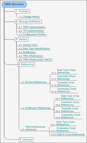
The typical DMS consists of 28 main pages nested as below:
3.1 Overview Page
This page gives a brief description of the purpose and aims of the message flows for the domain.
3.2 Change History Page
This page gives details of all the changes that have been made to the specification.
3.3 Message Definitions Page
This page details the message(s) that are used by this domain, below is a typical message table.
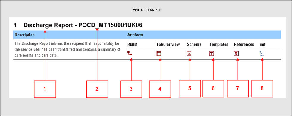
- Message name.
- Message identifier.
- Link to the R-MIM (message model).
- Link to the tabular view (which is the message model documentation).
- Link to the message XML schema used for validation of message instances. The actual format / use of this schema will vary dependant on whether the message is CDA (2 levels of validation) or Non CDA (single level of validation). The Interaction table will provide more detail in this area.
- Link to the list of templates used by this message (where templates are utilised in the message).
- Link to the list of reference templates used by this message (where templates are utilised in the message).
- A link to the MIF (XML representation of the message).
3.4 TMS Implementation Page
This page details information about implementing the domain over TMS, a typical page is explained below:
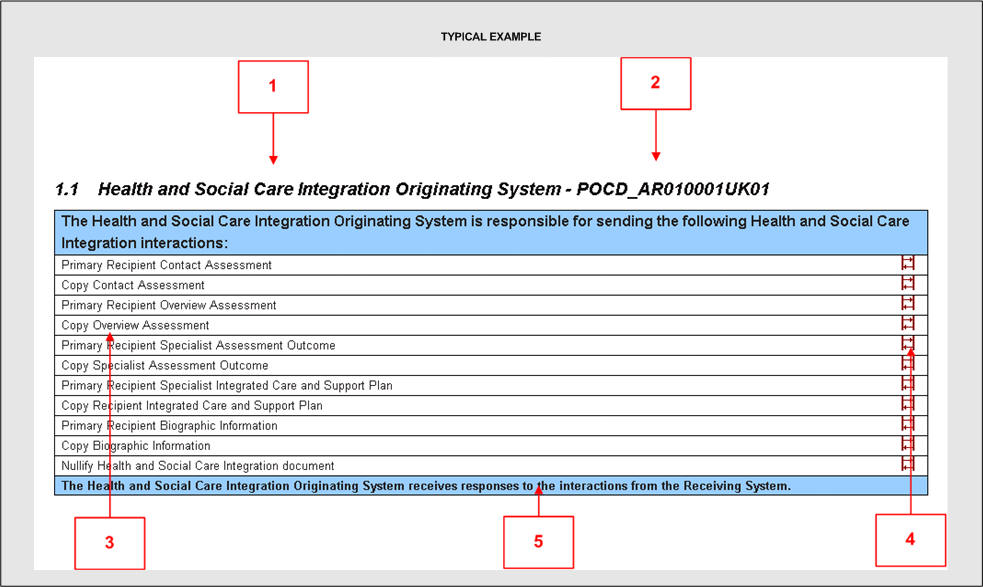
3.4.1 Application Role table
The first section details the application roles, this is detail about the role a particular system plays in the information flows.
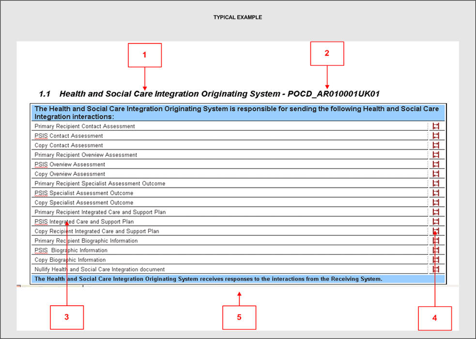
- The application role name - a description of the type of role, in this example this is the system where the information came from (the sending system).
- The application role identifier - a unique identifier of the role.
- A list of interactions that the role should support.
- These icons link to the interaction stated on the left.
- The cell at the bottom is used to indicate whether there is any additional behaviour required.
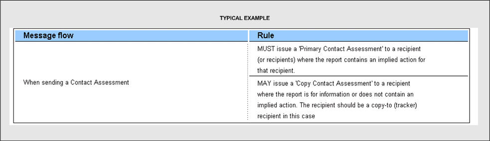
3.4.2 Application Role Rule Table
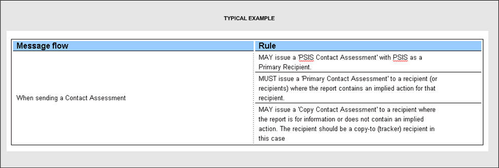
The application role rule table details rules the system which is playing the application role should obey, a typical rule is shown below:
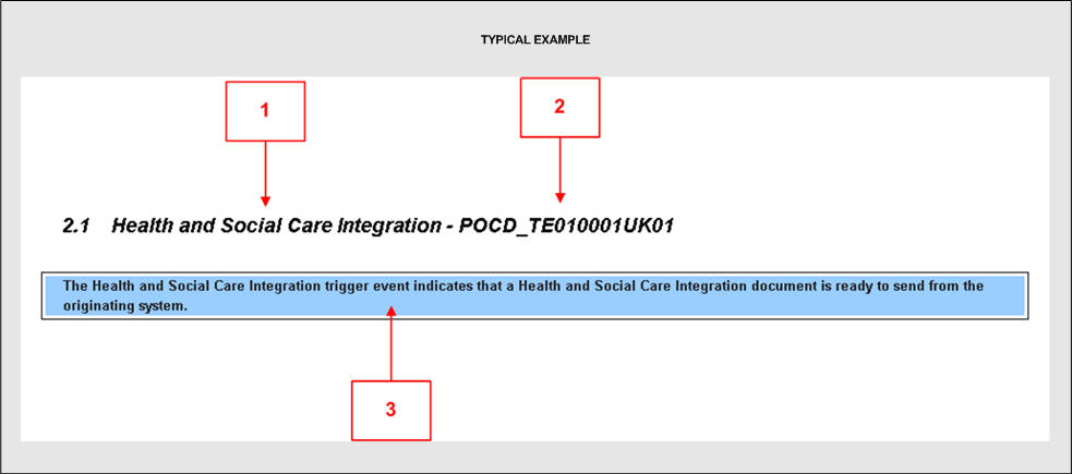
3.4.3 Trigger Events
The second section details trigger events - this is something that triggers an exchange of information, a typical trigger event is explained below:
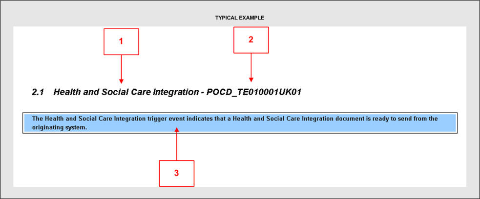
- Trigger event name.
- Trigger event identifier - a unique identifier of the trigger event.
- Details of the trigger event.
3.4.4 Interaction Diagrams
The interaction diagram gives a simple visual overview of how the application roles exchange information with each other, a typical diagram is shown below:
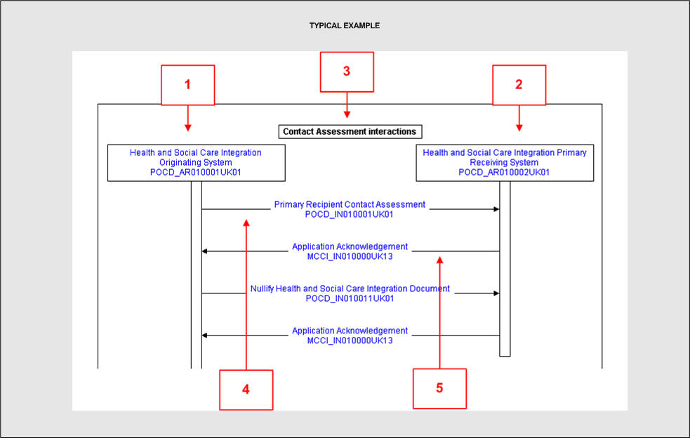
- The first application role - in this example this is the sending system.
- The second application role - in this example the receiving system.
- A description of the type of information flow.
- The interaction involved - arrow gives direction of information flow, in this example information (a contact assessment) flows from left to right , from sending (originating) system to receiving system.
- The interaction involved - arrow gives direction of information flow, in this example information (an acknowledgement) flows from right to left, from receiving system to (originating) system. It should be noted that both systems actually send and receive interactions. Most application roles are named based on the business information flow direction and things such as acknowledgements are not class as business information but as system responses.
Note : the interaction flows (the arrows) have no order or conformance. This means that interactions flow does not start at the top and go in the order downwards. Also the inclusion of an interaction does not mandate it.
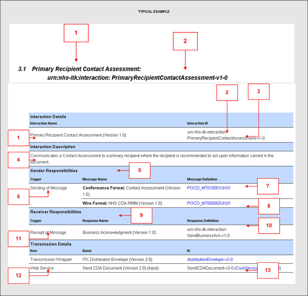
3.4.5 Interaction Tables
The interaction table details:
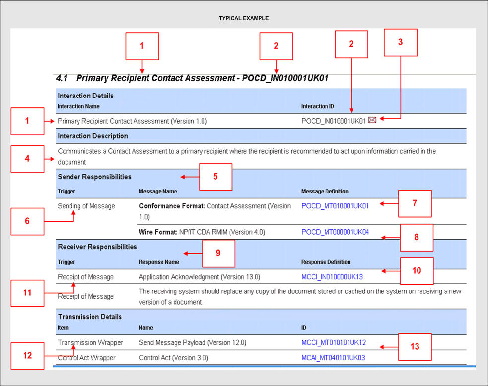
- Interaction name.
- Interaction identifier.
- Icon that links to the interaction schema - this is an XML file which validates the message and its TMS wrapper instance.
- Description of the interaction.
- Sender responsibilities - what the sender should do before they send the information, in this case they must make sure the information carried in the message payload is valid against the two artefacts stated ( see item 7 & 8 below).
- Trigger- what action triggers these sending responsibilities.
- The conformance format - in this case the message must be a valid POCD_MT010001UK01 message , i.e. a valid Contact Assessment when tested using the conformance rules for this message - the blue text links to the artefacts associated with this validation.
- The validation that the on the wire message must conform to - Note this is a CDA message and has two levels of validation. What this means is that the message must be a valid message when tested by whatever means is mandated.- the blue text links to the artefacts associated with this validation.
- Receiver responsibilities - what the receiver must do when they receive the message.
- What they must do when they receive the message - in this example send back an acknowledgement - the blue text links to the acknowledgement artefacts.
- The trigger for these responsibilities - in this example when they receive the contact assessment.
- The artefacts used for transmission - in this case the TMS wrappers.
- These are the artefacts used to wrap the payload information to allow transmission - in this example these are the TMS wrappers and this artefacts are linked by the blue text.
3.4.6 Message Examples Table
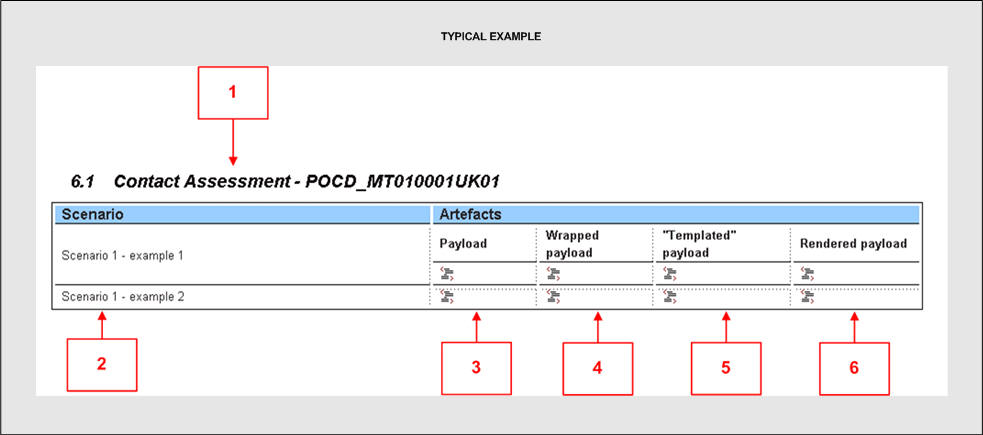
- The message type the example(s) are for.
- The business scenario that the example is based on.
- An example payload (message).
- An example of the payload (message) with its transmission wrapper in the format that is used "on the wire" i.e. with its TMS wrapper.
- A conformance testable version of the payload (in the case of CDA payloads the "on the wire" format is transformed into a conformance format for more rigorous testing).
- The payload rendered into a human readable form - this only applies to CDA documents.
3.5 ITK Implementation Page
This page details information about implementing the domain over ITK, a typical page is explained below:
Note: implementation over ITK refers to a payload wrapped in the ITK distribution envelope and not by any one transmission method.
3.5.1 Application Role table
The first section details the application roles, these are details about the role a particular system plays in the information flows.
-
The application role name - a description of the type of role, in this example this is the system where the information came from (the sending system).
-
The application role identifier - a unique identifier of the role.
-
A list of interactions that the role should support.
-
These icons link to the interaction stated on the left.
-
The cell at the bottom is used to indicate whether there is any additional behaviour required.
3.5.2 Application Role Rule Table
The application role rule table details rules the system which is playing the application role should obey, a typical rule is listed below:
3.5.3 Trigger Events
The second section details trigger events - this is something that triggers an exchange of information, a typical trigger event is explained below:
-
Trigger event name.
-
Trigger event identifier - a unique identifier of the trigger event.
-
Details of the trigger event.
3.5.4 Interaction Diagrams
Note interaction diagrams are not currently supplied for ITK implementation
3.5.5 Interaction Tables
The interaction table details:
-
Interaction name.
-
Interaction identifier.
-
Note ITK does not use interaction schemas compared to TMS and so there is no icon.
-
Description of the interaction.
-
Sender responsibilities - what the sender should do before they send the information, in this case they must make sure the information carried in the message payload is valid against the two artefacts stated ( see item 7 & 8 below).
-
Trigger- what action triggers these sending responsibilities.
-
The conformance format - in this case the message must be a valid POCD_MT010001UK01 message , i.e. a valid Contact Assessment when tested using the conformance rules for this message - the blue text links to the artefacts associated with this validation.
-
The validation that the on the wire message must conform to - Note this is a CDA message and has two levels of validation. What this means is that the message must be a valid message when tested by whatever means is mandated.- the blue text links to the artefacts associated with this validation.
-
Receiver responsibilities - what the receiver must do when they receive the message.
-
What they must do when they receive the message - in this example send back an ITK business acknowledgement - details of these business acknowledgements are available from the core ITK specification.
-
The trigger for these responsibilities - in this example when they receive the contact assessment.
-
The artefacts used for transmission - in this case the ITK wrappers.
-
These artefacts are used to wrap the payload information to allow transmission - in this example these are the Distribution Envelope (distributionEnvelope-v2-0) and the ITK Service (SendCDADocument-v2-0). These artefacts are linked by the blue text.
3.5.6 Message Examples Table

-
The message type the example(s) are for.
-
The business scenario that the example is based on.
-
An example payload (message).
-
An example of the payload (message) with its transmission wrapper in the format that is used "on the wire" , i.e. with its ITK wrapper.
-
A conformance testable version of the payload (in the case of CDA payloads the "on the wire" format is transform into a conformance format for more rigorous testing).
-
The payload rendered into a human readable form - this only applies to CDA documents.
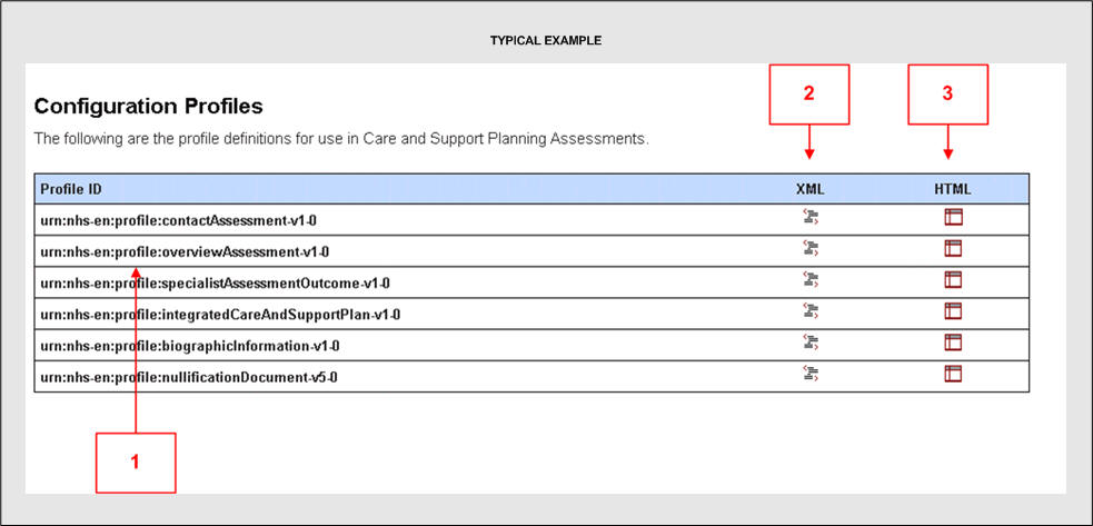
3.6 Configuration Profiles Page
The configuration profiles are a list of configurable items in the message, this means things that are able to change and therefore need some form of configuration management. These profiles currently only contain vocabularies and templates.
3.7 Generic Page
This page is a list of generic specifications included within the DMS, these generic artefacts are used across many domains. The following 5 sections detail what these are and there usage.
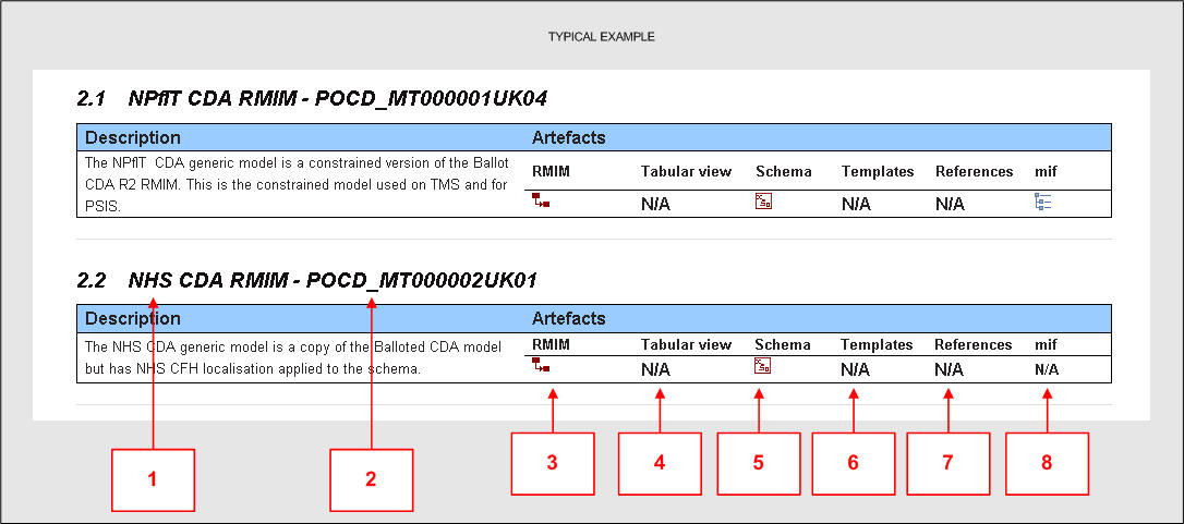
3.8 Generic CDA Page
3.8.1 Generic Models
The generic models are used across all domains to give consistency. These generic models are never implemented on the wire, but are used for level one validation. It is advised that vendors build in support for the generic model applicable to the domain to future proof any implementation. The domain models contained in the DMS will be a constraint of these generic models. i.e. will impose more rules.
-
Generic model name.
-
Generic Model identifier.
-
Link to the Generic R-MIM (model).
-
Link to the tabular view - there are no tabular views for generic models.
-
Link to the message XML schema used for validation of message instances on the wire (Level 1).
-
Link to the list of templates - Generic model do not use templates.
-
Link to the list of reference templates - Generic model do not use references.
-
A link to the MIF (XML representation of the message) - Note not all generic models have a MIF.
3.9 Data Type Specifications Page
This page details the data type specification and the flavours (sub types of data types) in use.
3.10 Nullification Page
This section of the DMS specifies the generic document to be used to nullify (withdraw) an incorrect document when a correcting document is not available.
3.11 TMS Infrastructure Page
This section of the DMS specifies the wrapper used when using TMS.
3.12 TMS Infrastructure CMETs Page
This section of the DMS specifies the CMETs (reusable models) used by the TMS wrappers.
3.13 References Page
This page lists the reference files available, reference files are made available for vendors to do analysis across messages, domains and message specifications. These can be use for such things as evaluating the impact of a change to a vocabulary or template.
3.14 Domain References Page
This page provides links to the following domain reference page.
- Data Type Cross Reference.
- Constraint Cross Reference.
- Template Cross Reference.
- Vocabulary Cross Reference.
3.14.1 Data Type Cross References Page
This page details the data types used by the domain and where they are used in the messages.
3.14.2 Constraint Cross References Page
This page details the constraints (list of templates) used by the domain and where they are used in the messages.
3.14.3 Template Cross References Page
This page details the templates used by the domain and where they are used in the messages.
3.14.4 Vocabulary Cross References Page
This page details the vocabularies used by the domain and where they are used in the messages.
3.15 Nullification References Page
This page provides links to the following nullification reference page.
- Data Type Cross Reference.
- Constraint Cross Reference.
- Template Cross Reference.
- Vocabulary Cross Reference.
3.15.1 Data Type Cross References Page
This page details the data types used by nullification and where they are used in the nullification message.
3.15.2 Constraint Cross References Page
This page details the constraints (list of templates) used by nullification and where they are used in the message.
3.15.3 Template Cross References Page
This page details the templates used by nullification and where they are used in the message.
3.15.4 Vocabulary Cross References Page
This page details the vocabularies used by the nullification and where they are used in the message.
3.16 TMS Infrastructure References Page
This page provides links to the following Infrastructure reference pages.
- Data Type Cross Reference.
- Constraint Cross Reference.
- Template Cross Reference.
- Vocabulary Cross Reference.
3.16.1 Data Type Cross References Page
This page details the data types used by TMS Infrastructure and where they are used in the Infrastructure wrappers.
3.16.2 Vocabulary Cross References Page
This page details the vocabularies used by TMS Infrastructure and where they are used in the Infrastructure wrappers.
3.16.3 CMETs Cross References Page
This page details the CMETs used by TMS Infrastructure and where they are used in the Infrastructure wrappers.
3.17 Glossary Page
This page gives an explanation of the terms used within the DMS.
4 Icon Meaning
Icon Meaning
R-MIM
Tabular View
Schema
Example Message
TMS Interaction Schema
Interaction
Model Template List
Model Reference List
Mif
Role Constraint
Section Constraint
Constraint Cross Reference
eXtensible Stylesheet Language Transform
Guidance